Understanding 3D Camera Tracking: From Reality to Reconstruction
[BY]
Shameek Khandokar Monon
[Category]
Tips & Tricks
[DATE]
Oct 17, 2023

Unlock the secrets behind industry-standard match-moving in this comprehensive guide. While focusing on the powerful workflow of PFTrack, this tutorial breaks down the core fundamentals that apply to every 3D tracking software, including After Effects and Blender. From critical footage preparation—like avoiding speed ramps and using image sequences—to mastering the "Static World" rule through masking and solving, learn how to reverse-engineer reality and achieve a perfect, slip-free 3D track every time. Whether you are a beginner or a pro, this guide provides the roadmap to getting that coveted sub-1.0 pixel error.
Imagine a surveyor standing in an open field. A tree stands nearby, a mountain far in the distance. When the surveyor steps sideways, the tree shifts noticeably in relation to the background, while the mountain appears almost stationary. This relative motion—known as parallax—is how the human brain infers depth and spatial scale.
3D camera tracking is the process of teaching software to interpret motion using the same physical principle.
By analyzing thousands of high-contrast points across a sequence of images, tracking software reconstructs the exact position, rotation, and focal properties of the camera for every frame. The result is a virtual camera that mirrors the real one with high precision, allowing digital objects to exist convincingly within filmed footage.
The Tools Behind the Math
While the underlying mathematics are universal, the level of control varies between tools.
Dedicated Solvers (Industry Standard)
PFTrack, 3DEqualizer, and SynthEyes are purpose-built camera tracking applications. They provide deep access to lens models, solver behavior, and track management. These tools are the standard in feature film and high-end VFX pipelines.
Integrated Trackers
After Effects, Blender, Nuke, and DaVinci Resolve include camera tracking as part of a broader toolset. They are efficient for straightforward shots but offer limited diagnostic and corrective capabilities when dealing with complex footage.
Phase 1: Preparation — The Invisible Work
Successful tracking is largely determined before any software is opened.
Constant Speed Footage Is Non-Negotiable
Camera tracking assumes linear time and physical motion. Speed ramps violate this assumption. When footage is artificially slowed or accelerated, the tracker interprets the altered motion as changes in camera velocity or scene scale, corrupting the parallax calculation.
Best Practice
Track the original, unmodified footage. Apply speed ramps only after 3D elements have been placed and rendered.
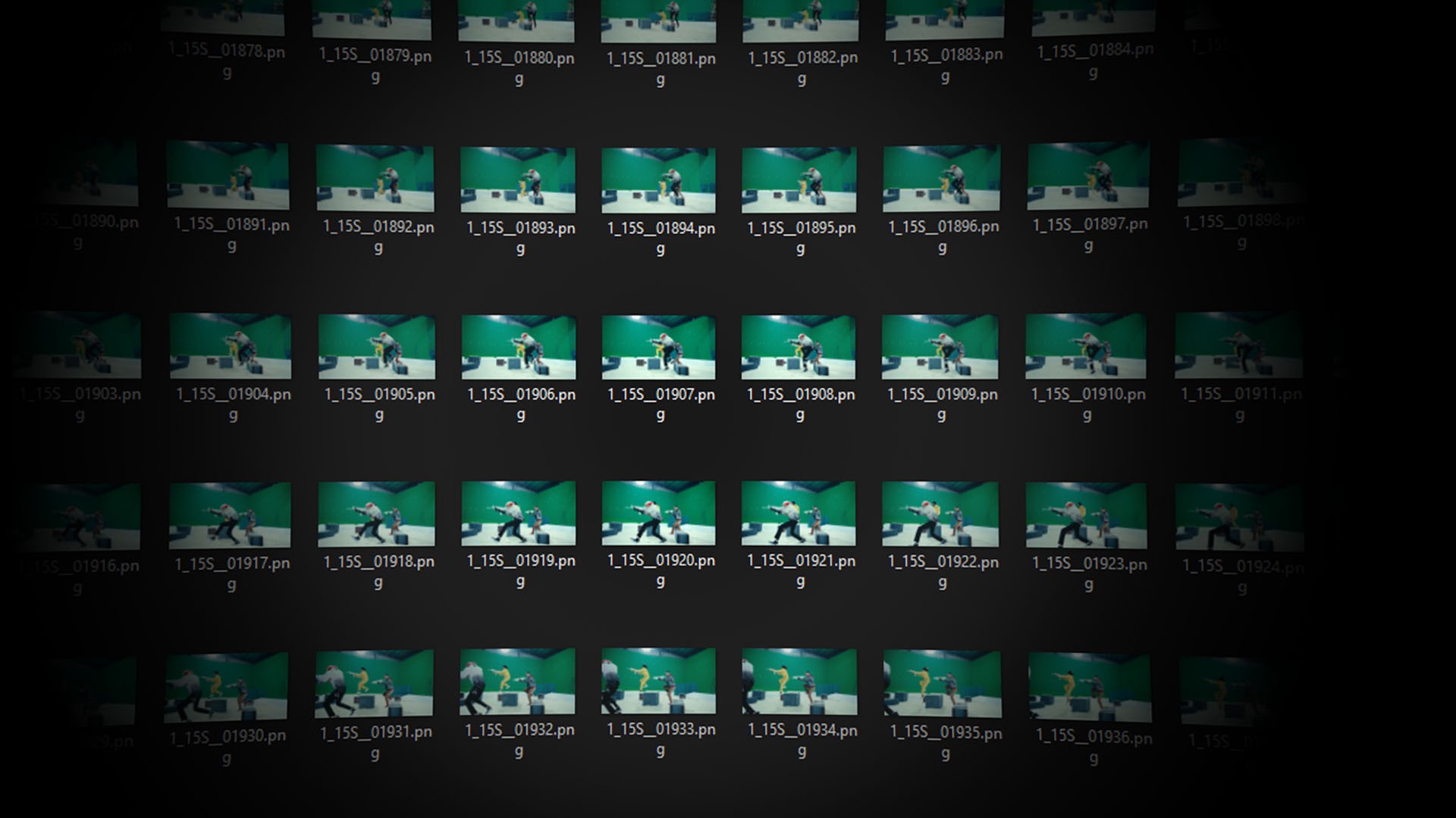
Image Sequences Over Video Files
Compressed video formats such as MP4 or MOV rely on inter-frame compression, where frames are reconstructed from differences rather than stored independently. This introduces compression artifacts that degrade point detection and tracking stability.
Best Practice
Use image sequences such as PNG or EXR. Each frame is a complete, uncompressed image, providing clean data for the tracker.
Phase 2: Solving the Camera in PFTrack
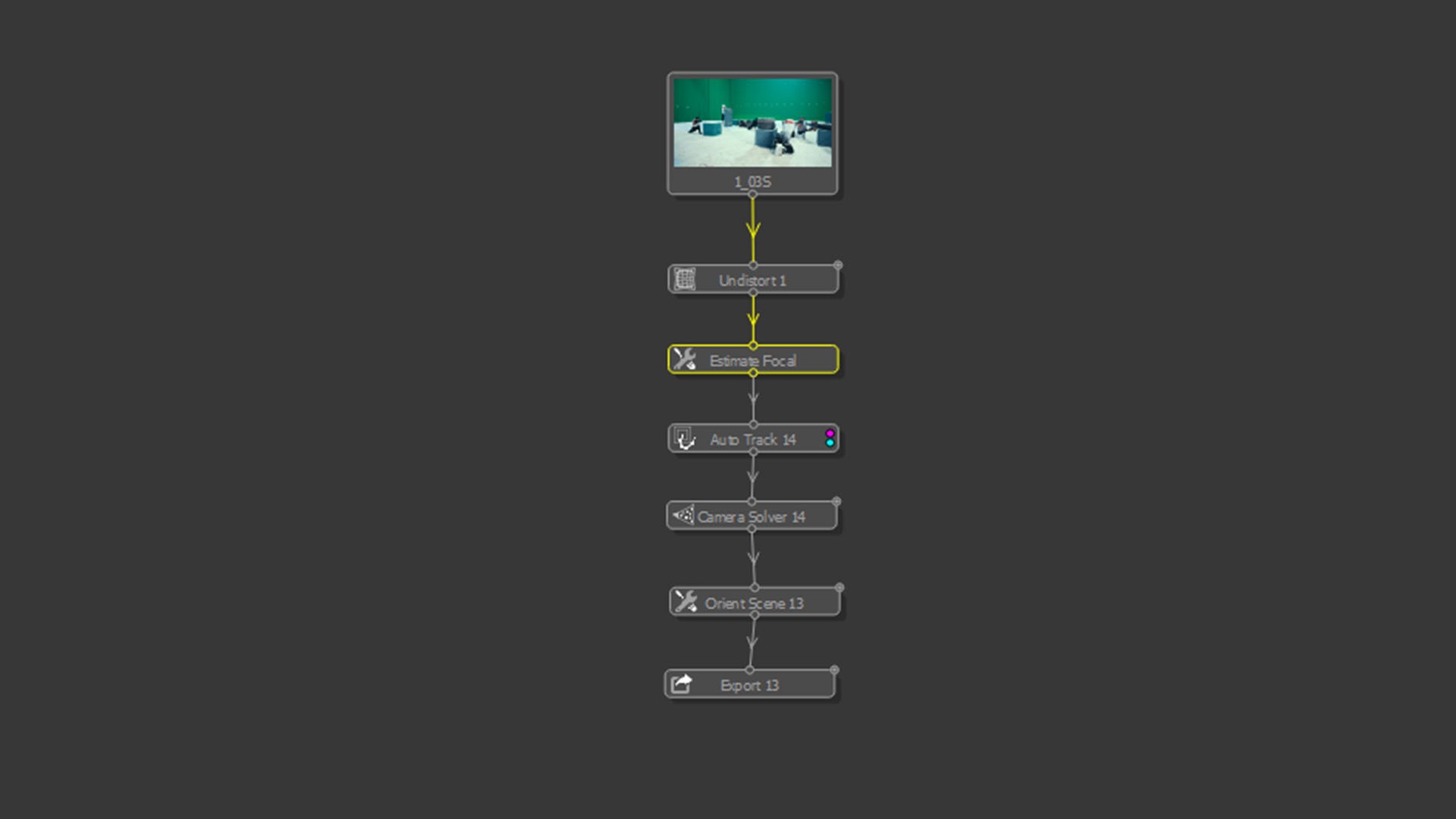
The typical PFTrack workflow follows this structure:
Undistort → Estimate Focal Length → Auto Track → Solve → Orient
Lens Distortion and Focal Length
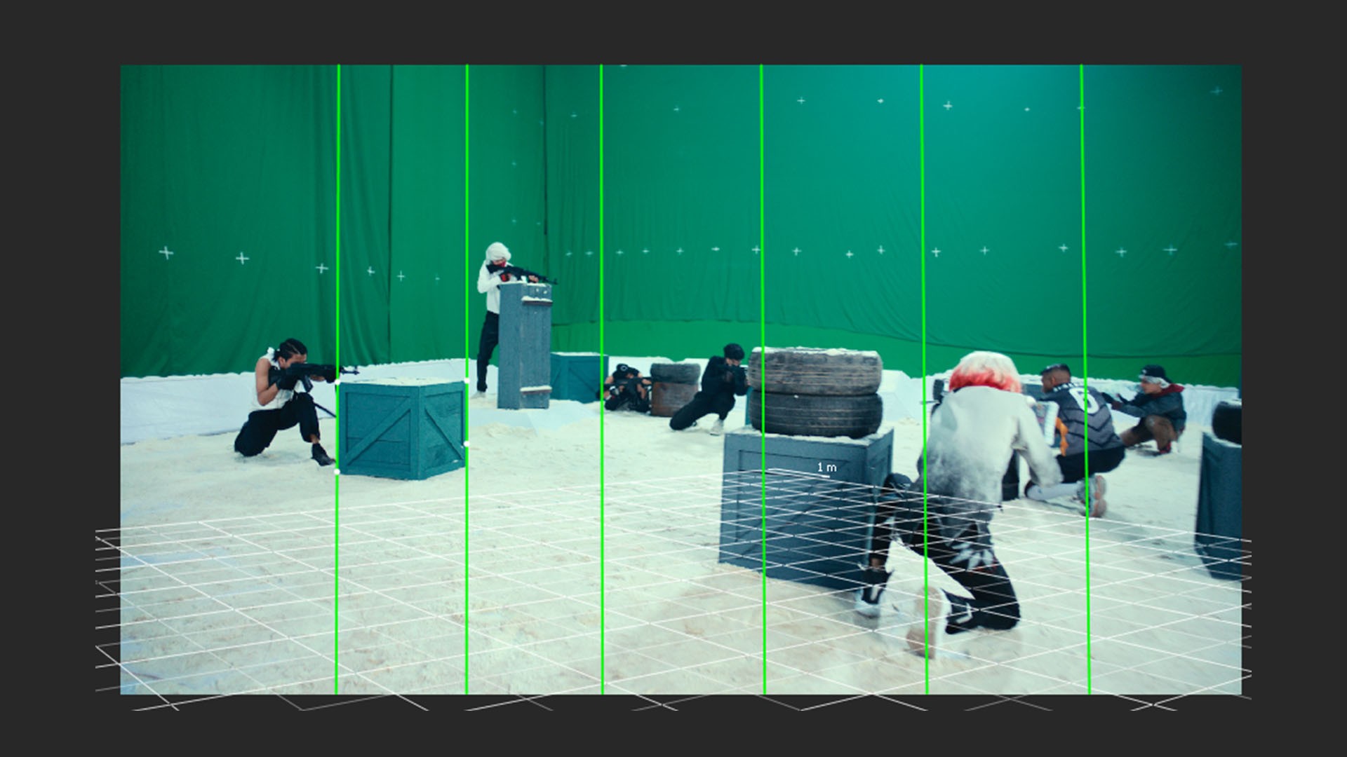
Real-world lenses introduce distortion. Straight lines bend, especially near the edges of the frame. If uncorrected, the solver is forced to reconcile curved geometry with linear math—an impossible task.
Using vanishing lines on real-world straight edges (walls, floors, buildings), PFTrack calculates both the focal length and lens distortion model. Once undistorted, the image conforms to physical camera behavior, allowing accurate solving.
Masking: Enforcing a Static World
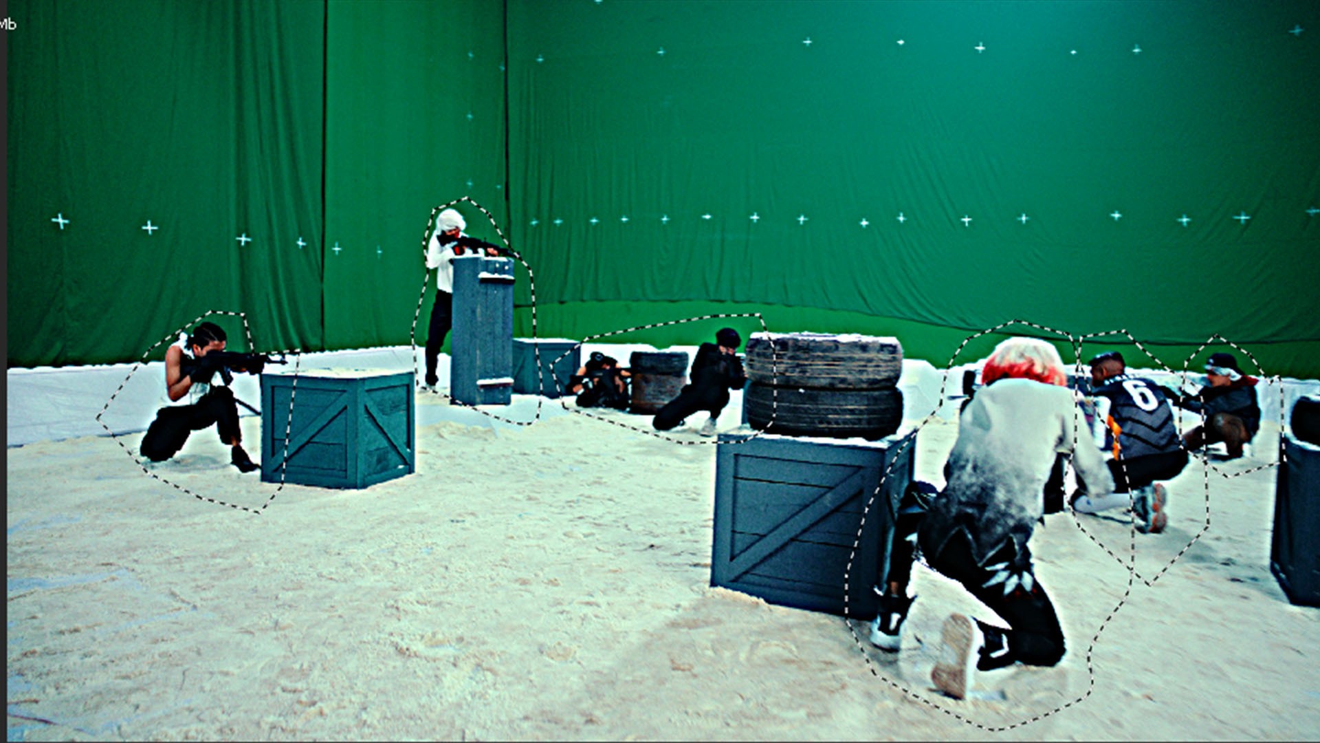
Camera solvers assume that the environment is static and only the camera moves. Any independently moving object violates this assumption.
Actors, vehicles, foliage, shadows, reflections—if tracked—will be interpreted as fixed points in space. The solver compensates by warping the camera path, leading to unstable or drifting results.
Best Practice
Mask out all non-static elements. The tracker should only analyze immovable geometry such as walls, ground, and structural features.
Auto Tracking and Image Enhancement
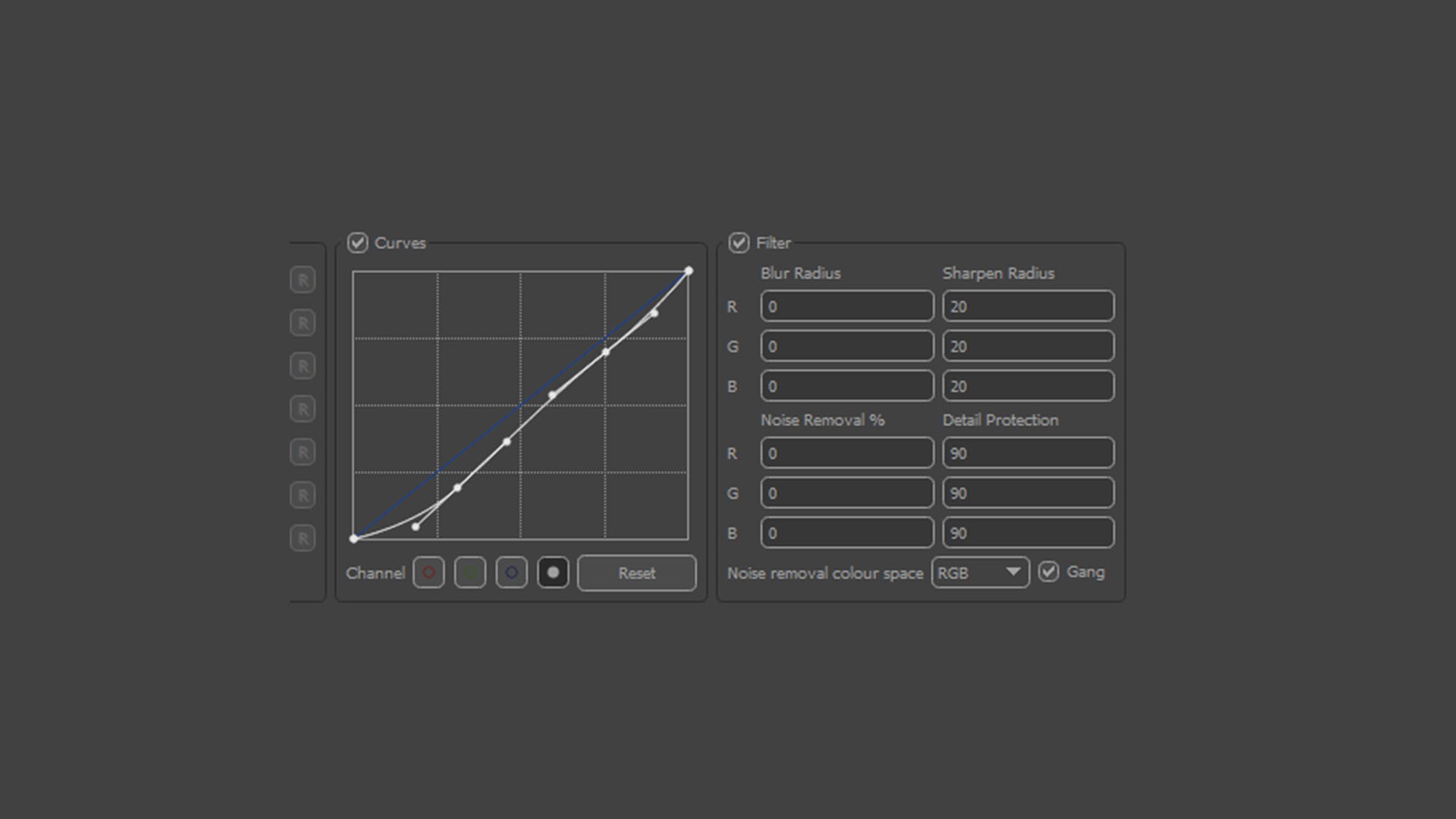
Auto tracking detects and follows contrast features over time. Trackers respond to luminance contrast, not semantic content.
Low-contrast or soft footage can be enhanced within PFTrack using gamma and contrast adjustments to strengthen feature visibility without altering the original image data.
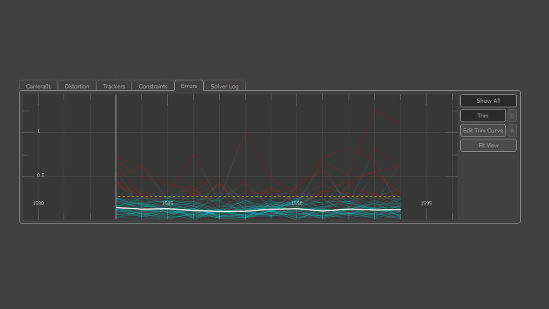
Solving and Error Analysis
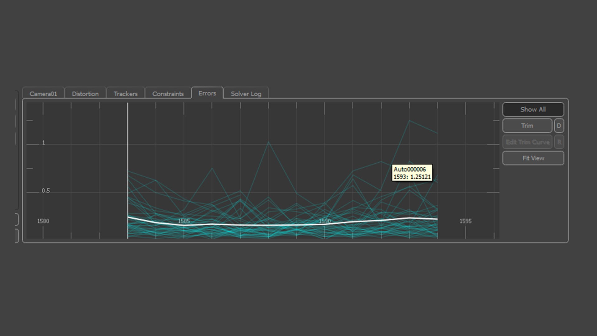
When the solver runs, it attempts to find a single 3D camera path that best explains the motion of all tracked points.
The error graph is critical:
White Line (RMS Error): Average pixel deviation. Values below 1.0 are acceptable; below 0.6 indicates a strong solve.
Red Spikes: Outliers caused by slipping or contaminated tracks.
Removing problematic tracks improves solver stability. This process is iterative and analytical—more akin to data cleaning than automation.
Orientation, Scale, and World Alignment

At this stage, the camera exists in abstract mathematical space. Orientation defines how that space relates to the real world.
Origin: Establishes a physical reference point, typically on the ground.
Ground Plane: Defines gravity and vertical alignment.
Scale: Converts arbitrary units into real-world measurements by defining known distances.
Without correct scale, objects may appear to float, slide, or move unnaturally even if the camera path is accurate.
Positioning 3D Objects Using Track Data
This step is where tracking becomes spatially meaningful.
Every solved track point represents a real location in the physical world that the camera observed. These points are the only reliable references you have—they are measurements, not guesses.
To place a 3D object correctly:
Select track points that lie on the same physical surface where the object should exist (for example, points on the ground or a wall).
Create a locator or reference null from these tracks.
Align and position the 3D object relative to that reference.
Objects should never be positioned arbitrarily. If an object is not anchored to real track data, it has no physical relationship to the environment. Even minor camera movement will expose this through sliding, drifting, or incorrect parallax.
In professional workflows, objects are always constrained to solved geometry or point-based references because those points define the reconstructed reality of the scene.
Conclusion
Camera tracking is not a button-driven process. It is an analytical discipline that combines physics, optics, and careful judgment. The software does not “understand” the scene—it infers structure from the quality of the data you provide.
Mastering camera tracking means learning how to feed the solver clean, truthful information and how to interpret its feedback critically. Once this logic is internalized, the principles apply across all software, regardless of interface or branding.
Professional Tip
Before exporting, place a simple 3D cube in the tracking scene, locked to ground-based track points. If the cube remains perfectly stable through the shot, the solve is reliable. Any sliding indicates unresolved error that must be addressed before production use.
Camera tracking, done properly, is not illusion—it is reconstruction.

